Axis Pipe Block
The Axis pipe block is the link between the logical and physical worlds, managing position data for a physical or simulated axis.

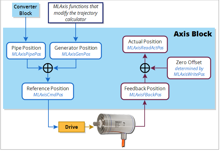
Figure 5-9: Axis Pipe Block Positions
Jump to a section on this page:
About Associated Data on Positions
The following data are illustrated in the figure below.
-
-
All positions are in user units with modulo applied if active, unless specified.
| Position / Offset | Description |
|---|---|
| Actual Position |
Actual Position refers to the actual position of the underlying axis as reported by the drive. It is the sum of the feedback value (Position actual value) returned from the communication link to the drive and any zero-offset due to an MLWritePos function block (MLAxisWritePipPos, MLAxisWritePos). ActualPos := FeedbackPos + ZeroOffset |
| Feedback Position | Feedback Position is the current position the drive reports for an axis, scaled to user units. It does not take into account the value of the Zero Offset or axis modulo. |
| Generator Position | Generator Position is the summation of all previous commands (i.e. calls to functions which perform motion such as MLAxisAbs, MLAxisMoveVel, and MLAxisRel) to the Axis internal motion generator. It is modified by MLAxisWritePos in order to insure no jumps in the Reference Position command. It also accumulates changes in pipe position due to activate and deactivation of the pipe the Axis block is associated with. |
| Pipe Position | The output of the convertor block is written into the Pipe Position value whenever the Convertor block is connected to the axis and the pipe is active. |
| Reference Position |
Reference Position is the commanded axis position sent to the drive. It is the summation of Pipe Position and Generator Position. ReferencePosition = Pipe Position + Generator Position |
| Zero Offset | The Zero Offset adjusts the coordinate system so that the Actual Position reports correct values after homing or using MLAxisWritePos. |
About Units
User Units (abbreviated UU) are the dimensions that will be used in the application code to define axis position or distance for an axis.
The "user units per revolution" field is used to set how many of these custom units are associated with one revolution of the motor. Some examples for this field are:
| User Units | User Units per Revolution Value | Notes |
|---|---|---|
| Degrees | 360.0 | |
| Gradians | 400.0 | |
| Radians | 3.14159265358979324 | |
| Inches | 15.7079632679489662 | This equals pi*5. This could represent the circumference of a 5 inch diameter drum. |
KAS standard units for velocity and acceleration are UU/sec and UU/sec2.
Functions That View Axis Block Positions
| MLAxisReadActPos | Returns the Actual Position |
| MLAxisCmdPos | Returns the Reference Position |
| MLAxisFBackPos | Returns the Feedback Position |
| MLAxisGenPos | Returns the Generator Position |
| MLAxisPipePos | Returns the PipePosition |
Functions That Change Axis Positions
| MLAxisAdd | This function adds a relative distance to the current target Generator Position. |
| MLAxisRel | This function adds a relative distance to the current Generator Position. |
| MLAxisAbs | This function sets a new target Generator Position. |
| MLAxisMoveVel | This function sets the generator position moving at a programmed speed. |
| MLAxisStop | This function stops any current Generator Motion. It also causes the axis to start ignoring any changes in Pipe position to be added into the reference position. It decelerates, if moving, at a programmed rate. |
| MLAxisReAlign | Causes the Axis to move by a programmed amount without changing the Reference Position following an MLAxisStop. Also allows the Pipe Position to be used following an MLAxisStop. |
| MLAxisWritePos | If convertor is not connected, Zero Pipe Position and Pipe Offset. If convertor is connected (pipe active also), the pipe position and offset are left alone. The actual position is then set equal to the target position, and the Zero Offset is adjusted for no motion. The Reference position and Generator Positions are then realigned so that the new reference position creates no step in motion, with the lag between reference position and actual position being absorbed in the generator position. |
| MLAxisWritePipPos | Changes the pipe position to be the new value. May cause a jump in motion. |
| MLCNVConnect | Initializes the pipe position to the Convertor block output value and adjusts the axis Pipe Offset so that no jump in motion is generated. |
| MLCNVDisconnect | Stops sending the convertor output to the Pipe Position, and disconnects the convertor from the axis. |
| MLPipeAct | Starts calculating Pipe data, If the convertor block is connected to the axis it will reconnect the convertor and start updating the pipe position. |
| MLPipeDeact | Stops sending Pipe data to the Axis Block Pipe Position and disconnects the convertor output from the axis. |
Axis Block Initialization
A call to the MLAxisInit function block is required to implement motion for the axis.
- All positions and offsets are set to zero
- The Axis Block motion generator is initialized with the proper ranges
- The values are "aligned": ReferencePosition = Pipe Position + Generator Position
Axis Connection to a Pipe
A call to the MLCNVConnect function block is required to get motion generated in the pipe to the Axis
- Pipe Offset is calculated as follows: Pipe Offset = Pipe Position – Reference Position
- The values are “aligned”: Reference Position = Pipe Position + Generator Position
Realigning Positions
A call to the MLAxisReAlign function block is used to realign the axis after an error occurs
- Motion must come to a stop first
- The MLAxisReAlign is executed
You must set the movement of this block to MLAxisReadActPos - MLAxisCmdPos - The target position must be reached before any additional motion can occur.
It can be checked by using the MLAxisReAlgnRdy function block
Set Zero Axis
A call to the MLAxisWritePos function block is used to set a position offset at the Axis when the Pipe Network is not yet connected
- Pipe Position and Pipe Offset are set to zero
- Generator Position is set to equal to Zero Position
(Zero Position is defined in MLAxisWritePos function block) - Then Reference Position equals Pipe Position + Generator Position
Homing
Homing is the process of moving the motor to a known physical reference point on the machine.
Homing can be performed with the MLFB_Home* Kollmorgen UDFBs or by adding custom application code that uses only the Motion Library - Axis function blocks. The PipeNetwork is typically not used in homing.
Custom homing is done with MLAxisRel and MLAxisAbs to make motion and MLAxisWritePos to set a position offset.
Single-Axis Operation
This includes motion done on an individual axis block: jogging, absolute move, or incremental moves. If these are single-axis based, then motion is executed with the MLAxisMoveVel, MLAxisAbs, and MLAxisRel FBs. These motions are typically done during machine setup or adjustment and are often referred to as manual mode. For these operations, the Pipe Network does not need to be connected to the axis.
Multi-Axis Operation
For multi-axis applications, automatic operation requires motion synchronization between two or more axes and the Pipe Network is required to achieve the synchronization. To start up the Pipe Network the following two function calls must be executed in an application program:
PipeNetwork(MLPN_ACTIVATE):
PipeNetwork(MLPN_CONNECT);
Multi-axis synchronized motion is then accomplished using a motion block associated with one of the three input Pipe Blocks:
- Master: MLMstRun, MLMstRel, and MLMstAbs
- PMP: MLPmpAbs, MLPmpRel
- Sampler: MLSmpConnect, MLSmpConECAT, MLSmpConPNAxis, MLSmpConPLCAxis
Monitoring an Axis
There are function blocks to monitor the performance and status of an axis. The key function blocks are as follows:
- MLAxisCmdPos - The commanded position to an axis.
- MLAxisReadActPos - The actual position of the axis.
- MLAxisStatus - The status of the axis. This includes information on the enabled/disabled state, bus connection, PipeNetwork connection, the drive executing an axis stop function, as well as other status information.
- MLAxisReadGenStatus - The status of the Axis generator: acceleration, run, deceleration, change designation point, single step.
- MLAxisGenIsRdy - Specifies whether the Axis generator is ready.


